Monday, September 29, 2014

Creating Homemade Refractory Bricks


"Refractory" is just a word that means "very resistant to high temperatures." In the context of pottery and glassmaking, I need refractory material for the lining of my kiln(s) I am going to make. Regular, pure clay doesn't cut it. I can also use refractory for making bricks to hold up pieces in the kiln or to use for making the actual walls of a kiln, if I want to make one out of entirely my own materials.

For either of these purposes, I need a substance that is actually not only refractory, but also insulating. That is, it should neither break down at high temperatures nor should it let heat get past it. Tungsten metal is highly refractory but a poor insulator. Cotton is not refractory (will burst into flames at maybe 400 degrees F) but is a great insulator.

Pure earthenware clay by itself is mediocre at both of these things by itself--it will slump and melt at moderately high temperatures, and it isn't actually that great of an insulator (Think about how quickly your mug gets too hot to touch on the outside when you pour coffee in it). So we want to improve these qualities for furnace materials.

Refractory recipes can get very complicated, but for mine, I want only locally available ingredients. I am going to have 3 ingredients: dry grass, quartz sand, and some of the clay I prepared earlier here.


  • The clay forms the main body of the material and holds everything together. It is also, of course, reasonably heat resistant.
  • The sand raises the melting point of the material significantly, since quartz melts about 500 degrees celsius higher than earthenware clay does (note: sand is locally available, but this particular batch used hardware store sand just for now). 
  • The oven-dried grass helps hold everything together at first, since the clay mixed with sand is crumblier than pure clay (see here [link]). Later, the grass will burn away in the kiln and leave lots of tiny air pockets that will help insulate against heat transfer.
  • ...another ingredient I could have added is wood ash. WASHED wood ash. I.e. the stuff left over after you have soaked new ashes in water and drained off the potash a few times (this will be the subject of an upcoming blog post, since potash is used for glass making and pottery glazes). Washed ash stuff is much more heat resistant than quartz, so replace a little or a lot of the sand with it, if it's available. It must be washed ash, though: raw ash contains potash, which is a chemical that actually lowers the melting point of quartz, and thus is counterproductive.
The ratio I'm using is about 50/50 clay and sand by volume and then about another equal part as the sum of the first two ingredients in dry grass by volume, loose (not packed!). In reality, it's probably something like 70/27/3 by mass for clay/sand/grass, but I don't know. It's easier for me to measure volume, so I'm just using that. Mix it all together, and you get something like this:


This is essentially adobe in it's raw form. You can build some pretty strong buildings out of this in dry climates if you let it bake in the sun for awhile, although you'd probably want more sand and grass in it.

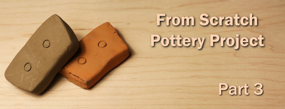
The adobe is much harder to work with than pure clay, but making things like bricks is still easy. Below are some examples of bricks that I made out of this material and then fired (I'll cover firing in a later post). Click for a larger size. As you can see, the grass has burned away and left them porous. These things are super lightweight and feel like pumice, and their insulation is probably excellent. Unlike the raw adobe, though, the fired bricks are also extremely brittle and easy to break, since the binding strength of the grass has been removed and now actually hurts the strength of the material by leaving air behind instead. 

The examples below actually used more like 60/65% sand, 35-40% clay by volume, and the fact that they are so brittle is why I'm now suggesting a 50/50 mixture instead (I also toned down the grass slightly from these bricks):


Notice the gray spots all over -- there was not enough oxygen and/or not enough time during firing. This is the same issue as that cheap hardware store pot I showed in an earlier post. It's not the end of the world, but it does increase brittleness even further, and I need to fix it. I'll discuss this more in my post(s) about firing clay.

You can also see a crack in the middle brick that formed just from roughly piling them in this stack! That's how brittle these are with the sand-heavy recipe... Again, use more clay than this (which I will be doing in the future).

HELPFUL LINKS

Probably the most popular recipe for homemade refractory online is this one:
A version using perlite for insulation and cement as well.
It does not use local materials though. Even less local and not homemade are commercial versions:
An example of hardware store refractory.

My own version is adapted from commercial versions and the backyard metal casting website, but substituting locally plausible materials (the sand and clay are literally locally gathered) to fill all the same roles in about the same ratios.

Thursday, September 25, 2014

Making a Homemade Pipe Organ


One of my long term crafting projects is to build my own working pipe organ. Do I know how to play the organ, you ask? The answer is no. No I do not. Why did you ask that? I hardly see it as relevant.

Moving on, this will be a "positive organ," or in other words, a small desk-sized one. In the layout below, the entire table there is about 4 foot by 2 foot, and the largest pipes are 2" in diameter and would just barely clear a typical apartment ceiling (top pipe in the splash image above). The color coding is for commercially available widths of PVC pipe, my primary building material:


I don't remember at all what made me interested in this project, but hopefully it will be capable of creating wonderful art when it's all done, whether or not I'm the one making art with it!

Overall, a pipe organ requires the following components, and thus these are the major areas of the project:
  1. A frame of some sort -- this can be anything from a modified table to a huge gilded architectural wing of a building. In my case, my most important design consideration is portability - I am keeping the organ small and desk-sized, and I want to be able to break it down for transportation.
  2. A lot of pipes -- My organ has five octaves (61 pipes) in flute-like sound, give or take a few pipes possibly for different harmonies at the end(s). One octave is a 2x difference in pipe length. You can "cheat" your way for one bonus octave without longer pipes by making ones with stoppers in the ends which effectively doubles the virtual length. Thus, my organ will have pipes from about 4 foot to 6 inches. They also get narrower as they get shorter. I am planning 2-3 additional redundant octaves in something much more fun. Tentatively, "bubble" sound. I.e. bubbling water, but in specific pitches. Because reasons.
  3. A keyboard (called a "manual" on an organ). This doesn't have to have a key for every tone, although it is convenient and mine will. The color coded keys above are ones that would be able to play either/both bubble and flute pipes, based on a pull-control knob (a "stop").
  4. A "wind" (air) supply, including some sort of fan or bellows, as well as a regulating reservoir to control for consistent pressure despite however many keys you are playing at once. Without a regulator, an 8-note chord would play 8x more softly than a single note. We want consistency, which requires building up a reserve of air pressure. i will use a squirrel cage electric fan and a box with a rising, weighted lid for a reservoir.
  5. A windchest, which is an interface that takes in the main air supply, and uses linkages from the keys and any number of control stops to distribute wind to the appropriate pipe or pipes.I plan to take advantage of plastic tubing to greatly reduce the mechanical complexity compared to traditional church organs. Basically all I need are some small boxes and flap valves for each key, and some airtight gaskets, and that's it. Possibly one sliding board to convert between flute and bubble pipe voices.
  6. Finish. Most of the pipes in my organ are going to be made out of PVC plastic plumbing pipe, so paint is a high priority to hide that fact. A tentative paint scheme is something like this (the arrangement of pipes here is not realistic, just slapped on the image):

(Possible paint scheme of my organ. An air pressure reservoir is on the floor. 
The tube sections on top of the pipes are tuning slides.)

In my next post for this project, I'll dive right into the design and airflow diagrams for individual organ pipes, which are all homemade here, mostly out of PVC.

In the meantime, here's a sound clip of the four pipes from the splash image. In order from the top: 1,2,4,3. Sorry, the highest note is a bit wheezy and cracks its voice--it's not the pipe, it's just that I can't play it as hard as it is designed for without blowing out the audio on my microphone. At normal strength, it is crisp.


    HELPFUL LINKS

    I'd like to extend deep thanks Raphi Giangiulio, who I have never written or talked to myself, but whose website about homemade organ building has been my #1 go-to resource for this project so far: Mr. Giangiulio's homemade pipe organ. Here's a sound sample using flue pipes similar in construction to what I have planned (mine would be less warm and rich): Giangiulio sound sample

    Matthias Wandel's project has also been especially helpful as an inspiration: A less ambitious but still awesome homemade pipe organ

    (I don't think either of these guys knew how to play the organ either, by the way!)

    Sunday, September 21, 2014

    Restoring an Antique German Typewriter


    Laptops are for suckers. Why put up with the hassles of a cord and wall outlets, when you can enjoy the unfettered freedom of a 40 pound block of manually operated, electricity free cast iron?! Also, if you start taking mortar fire while typing a memo, this guy's got you covered:


    Unfortunately, this circa 1905 Kaiser-approved German desktop typewriter arrived in rough shape fresh from UPS. It needs a lot of TLC before we can even attempt to type with it, let alone rely on it or display it proudly as some beautiful, functional art.

    So... let's fix it! Repairing typewriters is a joyful experience in my opinion. Nowadays, most of the machines we use require computer diagnostics, etc. to even attempt to work on them. Even if you understand the mechanics of things like cars, there are fewer and fewer things you can fix or modify yourself as a hobbyist.

    With mechanical typewriters, you can fix almost anything with only some screwdrivers, oil, ingenuity, and gumption. I obviously have no formal training on these, but I can still figure it all out, because it's all just levers and springs, and you can reliably follow them around and puzzle it out in the end. It's a sometimes very challenging, yet an almost certainly solvable puzzle, and one that uses your eyes and hands -- the best kind!

    First, we begin with just testing the features:


    GENERAL CHECK OVER
    1. The keys, of course (A) - What happens when you hit them? Well, what happens is that a couple of them stick ("H" and "^"), and the rest make it about halfway to the platen (the rubberized striking surface at J), before they meet with mysterious bouncey resistance.
    2. The space bar (B) - It snapped in half, but the lever seems to function.
    3. Shifting (C) - The buttons seem to work, but the carriage (the whole top assembly) is jammed or messed up, so they don't really do what they are supposed to. I don't think it's the shift's fault, though, intuitively. This can be revisited later if necessary.
    4. Caps Lock (D) - Same as shifting.
    5. Carriage return lever - It moves the carriage, but it requires a stupid amount of force to do, like there's a lot of friction, about halfway across. It also makes a horrible grinding sound from the teeth skipping on the gears in the back (the rack gear S<->T with the teeth of the escapement mechanism P). 
    6. Margin release - It's hard to see, but it's a button that pops out at F, when you hit the right margin. You can push it and give yourself a couple more letters if you need them (shame on you you bad bad typist! *ruler smack*). This doesn't work, because it's not attached to anything in the back (N - see the empty hole at the top of the lever).
    7. Ribbon advancing - The ribbon holder (H) is supposed to move whenever you type a key. The knob at G reverses the direction. Both seem to work.
    8. Platen knobs (I) - This is used for manually turning from line to line. One is missing, the other is horribly deteriorated, but there are no mechanical issues, the parts just need replacing.
    9. The platen itself (J) - The rubber is in good shape!
    10. Lever that lets the carriage slide freely (K) - Has the same friction and grinding issues with the carriage, but I don't think this is a cause, since it's just a minor input.
    11. A bar is missing that is supposed to hold the paper down (based on internet photos of the same typewriter) at (L).
    12. The single/double/triple spacing selector (M) - There was a spring that kept this in place that was out of whack. It took 2 seconds to pop back in position, and this now works.
    13. The backspace function - This is disconnected in back just like the right margin is. It seems to be missing parts (O).
    14. The escapement and main spring assembly (P) - This is grinding against the rack gear above it, but I don't think it is the originator of the problem, because it looks solidly attached and whole, etc.
    15. Arms that hold paper (Q) - These work. There is some gross mildewy felt under them though.
    16. The bell is missing (area below N), but the adjustable clapper that is supposed to hit it works (R).
    General aesthetics -- Dusty and dirty. There are a few areas of uncontrollable rust, and a lot of minor rust. It should clean up pretty well, though, with some light abrasion and chemicals and elbow grease. The decals are in good shape (the back one and ribbon spools look awesome), the front one is dim but intact, and it seems to be behind a layer of flaky varnish or something. The side lettering is worn, but very easy to touch up. The paint looks great, I don't see many chips or flaws in the paint job. The keys are in mediocre shape. There's some stubborn tape or something on the top of the case.

    CARRIAGE DIAGNOSIS AND REPAIR

    Most of these issues can be steadily repaired and cleaned up one at a time. But the carriage issues are by far the highest priority. If they can't be fixed, the whole machine will always be useless, and so would any other repairs.

    The symptoms the carriage is exhibiting are increasing friction toward one side and grinding gears. Gradual friction implies that two large moving parts are not properly aligned. Grinding implies that gears are not aligned. My first thought was thus that a major rail somewhere was bent. Thankfully, I couldn't find anything like that!

    My next thought was that two or more large rails were just entirely not lined up, even though straight. For example, are screws holding the fram together missing? No. Is the FRAME straight (also not a great question to find yourself asking...). Turns out NO it isn't.  The frame has a difficult-to-see but large crack in the back near the foot (somewhat below point N in the above pictures):


    This is not good, however typewriters don't actually experiences THAT much stress. The frame can probably be fixed with just a really strong 2 part epoxy (I also considered drilling through and bolting, but the surface area isn't large enough). Before doing that, though, I got a small C-clamp and just dry-clamped the sections together. What happened was that the friction largely disappeared, but the gear grinding didn't, and some parts were still knocking into each other. I futzed around until I found where:


    A screwdriver just bent out the middle part by a couple of millimeters and it was fine (hopefully this doesn't mess up typing later! I don't think it will.). Next, the gear issue. Turns out that one of the two screws holding that rack gear on was rotten and the head fell apart when I tried to unscrew it (see points S and T above). Here is an over-dramatization of the rack being misaligned (in this photo it's entirely unattached not just loose) and the gear underneath it's supposed to interface with:


    These screws from 1905 Germany aren't exactly standard modern thread sizes. I tried the hardware store, but it seems to be something ridiculous like M3.5 threading x 5mm long?? So instead, I found a random set screw of the same threading that wasn't doing much from elsewhere on the typewriter (see the remaining screw on the other side):


    This screw was too long, so I clamped it in some vice grips and used my dremel to cut it down to the right size, then filed down the burrs on the end so it would thread (broken screw on the right):


    (in its new home)

    After fixing the rack, the carriage now moves smoothly (C-clamp still dry-fitted for now), and doesn't skip teeth. It does still have a couple of issues though. First of all, it's WAY too strong. I assume that somebody working on the typewriter in the past tried to ratchet up the power on the main spring to just FORCE their way past the friction from the broken frame (tsk tsk tsk!). As in, the entire typewriter was vibrating with force every time the rack gear moved at all. So I loosened the tension dramatically to make it safer and less damaging to the machine. I rocked this lever back and forth to slowly release tension one tooth at a time until the carriage was too weak to move forward. Then I re-strengthened it by a few teeth (you can just grab the wheel with your hand and turn it usually):


    Finally, the carriage seems to sort of randomly stop partway across, and keys now sometimes work, and sometimes don't. When it does stop, it's a "soft" stop. It's hard to explain, but having used typewriters a lot in the past, it "feels like the typewriter doesn't want me to go further" not that something is broken and binding.

    Sure enough, my intuition helped me figure out the problem after a bit of looking in the right places. Remember that margin release that was disconnected? Here's another photo of what should be there:


    That missing arm is supposed to help keep the lever to the left UNTIL you hit the actual right side margin. The spring at the bottom helps hold it to the left, but was never designed to do this all by itself. What was happening was that the lever was too weakly held in its current state and was wandering randomly to the right side, then the machine thought that I was at the margin now and then, and it was dutifully stopping anything from working. For now, I just slapped some rubber bands on to hold it to the left.

    SO now the carriage works! It moves one spot when you type a key all the way across and returns properly with good tension and no resistance. This is a big relief. The rest of the problems can definitely be addressed and are worth working on, now that the carriage works. I still want to keep it under observation while I fix some other things before I epoxy it, but we can move onto other things.

    OILING

    At this point, I also oiled the main rails and pulleys of the carriage. Oiling bars is always a good idea. Just be careful to not get oil in the springbox or in any very dense areas of machinery like the big block that holds all the typebars. Oil in hard to reach places can get gummed up and is very difficult to fix later. Getting it inside coiled spring is bad too.

    DO NOT use WD-40. Use a proper machine oil. Something like sewing machine oil would be best. I'm a little lazy, and I'm just using basic 3-in-1 oil, but it's still universes better than WD-40, which will seize up in no time and make a huge mess later.

    A dab will do you! I prefer to use an old toothbrush with a few drops of oil and not even pour any oil from the bottle directly on the machine at all. It leaves a medium-thin layer everywhere with no dripping into bad places.

    HELPFUL RESOURCES

    • The classic typewriter page has an excellent reference article on general amateur typewriter restoration.
    • The typewriter database provides year of manufacture estimates for most typewriter brand serial numbers and other identification images and resources.
    • The virtual typewriter museum similarly provides identification resources for a lesser number of machines, and for this one it had some very useful information about how parts are supposed to go together and what was missing on my own model.

    NEXT

    I need to finish up all the remaining more minor mechanical issues, fixing some linkages and fabricating a part or two (backspace, margins, missing and rusty knobs, making a new space bar, new feet, new ribbon, new bell, unstuck "^" key).

    There's also a LOT of cleaning to do - rust removal, cleaning crud and dust and grease in general, dealing with the weird varnish/tobacco mix or whatever is on the front plate, retouching gold lettering, polishing, waxing. At some point, I'll probably have to remove the surface panels and clean up individual typebars underneath too. Also, re-felting.

    A couple specific photos of things still left to fix that I didn't include earlier. Top: a super rusted and old rubber platen knob. Middle: A completely missing other platen knob. Bottom: Another view of the remaining knob and a lot of surface rust on other levers and things.


    Monday, September 15, 2014

    Geology Simulator - The Shape of the World

    (Part 1 HERE)


    THE SHAPE OF THE WORLD

    Earth is a sphere. Due to their inability to fit rectangular grids, spheres are really difficult to work with in a program, though. Also, I'm making this geology engine for games that use rectangular environments anyway. So I'm not going to use a spherical planet. Instead, I need a different shape that satisfies the following criteria:
    1. Easy to translate neatly into a rectangle or rectangular prism
    2. Convenient to write code for (well defined, orthogonal dimensions)
    3. Only one continuous surface, so that plates can smoothly glide anywhere and LOOK like they developed on a familiar spherical world
    The best shape I've discovered to fit the bill is a "torus." It looks like the image below. Notice that it has rectangular grid cells all the way around, nice perpendicular dimensions, no annoying poles where everything comes to a point, minimal distortion of the cells (which I can just ignore), and a single smooth surface:

    (image by Dave Burke)

    You can also turn a torus into a rectangle easily. Just slice along where the red arrow is and where the blue arrow is, unfold, and you have a rectangle of surface, or a rectangular prism if you keep the thickness. In fact, we don't even really have to run our program as a torus, we can just use a regular 2-dimensional matrix, where things that go off the edge are assumed to show up on the opposite side. This is just a another way of looking at (projecting) the skin of a torus:


    There are a few differences from a sphere for world simulating purposes. For one thing, cutting around either entire circumference (red or blue arrow or similar), unlike a sphere, does NOT divide the world into two plates. You need to make two cuts like that (red vs. blue plates below). Alternatively, you can carve out a chunk with one single border that does not wrap all the way around (green plate below):


    Rectangular and toroidal versions of the same
    tectonic plate situation (sorry the number of
    cells changes, ignore that)

    Another difference is that north and south are not destinations like on Earth, where you're as north or south as you can get. Instead, they are just like east and west: they're just directions of travel only, that go forever, looping around. The red arrows in the first image represent north and south, the blue arrows east and west.

    CLIMATE

    Finally, climate would be very different than on a spherical world, and climate matters for geology (glaciers, frost wedging rocks apart, etc.). I should only take this into account, though, if the game world is actually supposed to be a torus, not if I'm just trying to simulate a sphere. So I will probably just cheat and overlay a sphere's climate. But if it were actually supposed to be a torus, I believe it would look something like this:


    The inner portion hardly ever gets sun, and is permanently iced over. The top and bottom of the planet suffer extreme temperature swings, with the sun never setting for half the year, and in darkness the other (if tilted like Earth is). Temperatures might be near boiling and then a hundred below across seasons. Plants can't live here, so the rocks are barren (migratory species might spend some time in the area to breed or similar, and sealife is sustainable. Very hardy annual plants might survive). On the very outer edge, the climate would be similar to Earth's temperate zones (like Europe), but with a double speed cycle of seasons. This is easily survivable year-round, and plant life is sustained here.


    I'm no meteorologist, but the weather should also be different. The seasonal instead of daily temperature fluctuation would either make more extreme weather (due to the larger difference) or less (due to less turnover/mixing things up), I'm not sure. This is something to keep in mind if I want to simulate an actual torus world later when I get to erosion parts of the model.

    PROGRAMMING STUFF
    (Non-programmers: worth skimming, but don't worry about the details too much)

    Organization


    I'm writing this in C++, so in order to define the world's shape and behavior, we also have to start thinking about the world's major object classes. As of right now, I'm carving the physical world into the following organizational classes (there are also custom vector classes and things not mentioned):

    WORLD: The whole world stores the plates in it and its dimensions. It also keeps track of the time. It has many important methods involving interactions between plates, like actually determining how far plates move together, which boundaries subduct versus crumple, and how much pressure and resistance plates get from the direction they try to move in. 

    VOXEL: A voxel is a 3D cube that is the smallest size that would be seen during eventual gameplay. Such as a single block in Minecraft. These are not actually simulated during geological timescales.

    GOXEL: A goxel (geological voxel) is a 3D cube that is the smallest size considered during geological simulation. I'm likely to change how many voxels make one goxel as I go, and have it later be a user-defined parameter. 16x16x16 voxels is a good starting point. Goxels don't do much, they mainly just store information about material types, temperature, pressure, etc. and get pushed around by other methods.

    COLUMN: A column is the smallest size unit in the 2-dimensional rectangular projection of the world. It is a stack of some number of goxels (the thickness of the crust changes in different places around the world). Columns do various things as a unit that makes them a useful class. For example, they float on the mantle of the planet, and this can cause stresses that cause them to crack away from neighboring columns and cause fault lines. They're also convenient for erosion and other things, like efficiently swapping real estate between plates.

    PLATE: A plate is a collection of columns. It gets moved by the world object, but it does various other things itself, like checking the buildup of pressure under the crust to calculate the likelihood of splitting into two plates (more likely the bigger it is) it also checks for whether columns have managed to create so many fault lines that they have effectively made a new plate.

    REGION: Possibly a generic "region" superclass that has methods and variables relevant to keeping track of areas of the world that have other areas inside of them (i.e. all of the above except voxels).


    Input

    Whenever possible, I am going to attempt to make every constant number in the whole program come from a user-variable text file, which will be the main source of control and input, for a good combination of user friendliess and coder friendliness (I hate GUIs, especially in C++).

    Output

    I'm probably going to output as color coded image files or ASCII for now. One of my design principles is definitely to have all of the output be modularly separate from the simulation code, though, so other people could swap it all out later.

    NEXT TIME


    I'm going to try to tackle just plate tectonics alone first. Plates splitting, moving due to new rock in ocean ridges, slowing down as they smash into things, deciding to subduct or not, etc. I will keep track of crumpling or uplifting of rocks as just numbers for now stored in columns ("7" = more crumpled rock is sitting here than "3," etc.). Same for volcanism. I can use these to output colorful pictures and get an idea of whether it looks reasonable or not. Actually storing more useful versions of that information can come later.

    Wednesday, September 10, 2014

    A Geology Simulator for Game Worlds


    THE STATE OF THE ART IN SANDBOX WORLD GENERATION

    Unless you've been living under a rock for the last several years, I'm sure you've at least heard of the game Minecraft (and if you have been living under a rock, don't worry: you've been getting a very similar experience). 

    The game uses a procedurally generated 3D world of blocks. You run around freely in a world that looks like the one below (default Minecraft) and dig and rearrange blocks to build things, such as the luxurious dirt hovel I put together especially for this blog post.

    (Terrain generator by Markus "Notch" Persson)

    (Built by yours truly! I also made this, by the way.)

    I played minecraft for several years, as part of a server full of 20-40 year old nerds (the Voxelbox). We were not terribly impressed by the default gameplay, controls, or creative options. However, we did recognize an excellent core concept and a very modifiable set of bones to the game. We went about making a variety of tools to ease the creative process, allowing of course infinite free blocks, building from a distance, boolean shape logic, smoothing operations over thousands of blocks at a time, etc. Basically, the goal was 3D multiplayer photoshop. We eventually ended up being able to make landscapes like this:

    or


    BUT CAN I PLAY IN IT?

    As nice as these end up looking (for a voxel engine), they doesn't really function as anything more than essentially a 3D painting on the wall. What if we still want to play the actual game?
    • The custom landscaping is only a thin veneer for looks. You could never play an actual game on this landscape that involved any sort of digging under the surface. It's all just solid gray down there.
    • It still takes hours of hand sculpting to make a section of land like this. It's fine for a proscribed experience like Skyrim, but not procedural games.
    • They're made by fantasy artists, not people who actually know anything about geology (or biology), so these scenes still tend to lack a lot of realism even at the surface, something a mining sandbox game should probably care about.
    What if we just forget it when we want to play the game, and use the vanilla terrain generator? Well, even though Minecraft does a somewhat decent job of procedural surface terrain, its underground situation is just plain terrible. When you cut open the world, it's little more than a random jumble of uniform gray "stone" and caves and such. Clearly this has no geological realism to it:


    Considering that the game involves spending a huge amount of your time underground--you know, mining--this becomes a serious drawback of game design.  Other games, like Dwarf Fortress also heavily focus on 3D procedural worlds. Dwarf fortress does a better job of realism, including some layers and stone types in somewhat reasonable locations:

    (Terrain engine compliments of Tarn Adams)

    ...But we are still looking at completely flat, fairly random jumbles of rock types, mostly shallow, rounded, boring mountains, perfectly straight vertical volcanoes/tubes pasted abruptly into the landscape with only 3 feet of obsidian around them, and no correspondence to any broader geological history, other than putting the broadest categories of rock in roughly the right order.

    A significant improvement is needed. I plan to attempt this by making a terrain generator that simulates actual geology, rather than faking an end product with simple fractals like these games do. If successful, this should exceed the realism, variety, and gameplay richness of the current leading games in the sandbox genre for world generation, both above and below ground.


    TO MAKE A REALISTIC GEOLOGY ENGINE FOR GAME WORLDS


    I am planning on implementing the following features for a geology simulator:
    • Proper plate tectonic-based continental history. Actual world plates will move around in a simulated history, collide, subduct, join together, break apart again, etc., forming realistic mountain ranges and continental shapes and compositions.
    • Bouyancy of plates causing bending, uplift, and fault lines.
    • Rock strata that curve in 3D when appropriate, for example when plates crumple together.
    • All continents come from somewhere. The world begins as all oceanic plates, and any continent can trace its history back to simulated volcanism, uplift, etc.
    • Realistic volcanism, with volcanoes of different types appropriately existing along corresponding plate boundaries. 
    • Magma is modeled underground and may not reach the surface, instead bubbling up in intrusive plutons that solidify into granite for example.
    • Metamorphism occurs from actual simulated pressure or heat from geological events.
    • Erosion follows (simplified) watercourses, weather patterns, and frost wedging.
    • Different rock types weather differently, leading to certain interesting and realistic features like Yosemite's Half Dome.
    • A rough simulation of life as it is relevant to geological history at first (for iron oxidation, mass extinction coal and oil layers, limestone formation, etc.), as well as more detailed climate and biome types added at the very end of the simulation.

    The goal is to get cross sections that look more like the below image, with obvious geological features like this old, solidified lava tube, volcanic cone, sedimentary rocks filling in above over time, and the oldest rock strata down below pushed apart into curved blisters when the ancient magma forced its way between them:


    (pixelated version: this is lower resolution than would be used)


    NEXT UP IN THIS PROJECT

    I'll lay out my plans for the basic framework of the world (and of the program, written in C++), including the main data storage types, the shape of the planet, and some other high level planning.

    Later on, I'll dive into large scale plate tectonics by themselves as the first major benchmark to get working.