Showing posts with label DIY. Show all posts

Sunday, March 6, 2016

View Camera and a Darkroom in a Small Apartment

Although I haven't written about it on this blog yet, I have been an avid (amateur) photographer for many years. I certainly enjoy the conventional artistic side of it, composing and mindfully lighting a beautiful image. But like most things, a lot of my enjoyment also comes out of trying to deeply understand the technical aspects, getting my hands dirty doing as much of the process myself as I can, and mechanically modifying things.

I of course own a digital camera, but my favorite camera by far is this 5x4" sheet film view camera. Looks old-timey, but I actually bought it manufactured new. Some quick snapshots:


The basic principle is that you point the camera at a subject, then use knobs to move the entire lens (just that little thing on the very front) to focus, the accordion part expanding or contracting as needed to keep the inside of the camera dark. The frosted / ground glass on the back (with grid, shown) then shows a faint image of whatever you are aiming at, and you can use this to ensure focus is correct. Putting a fabric hood over your head like you often see people doing with camera like this helps see this focusing image better. Disregard the tilting and pivoting of the lens for now, I'll discuss that some other time.

Once you're happy with your focus and composition, the whole panel with the glass tilts outward as a spring-loaded clamp, and you carefully insert a film holding device (shown below) into the clamp, so that the film holder is now held in between the glass and the body of the camera.

The film holder is designed so that once the glass panel is clamping it down, the film inside the holder is now positioned precisely as far from the lens as the glass USED to be, so that if the image was in focus when looking at the ground glass, it will be now on the film too.

The film holder consists of a frame, a central membrane, then then two (usually metal) "slides" with handles at the top. The photos below show modern ones (top, closed, slides in place) and an older one but easier to see the concept (bottom). In a darkroom, you pull a slide out, and feed a piece of film (5" x 4" sheet film, roughly the size of my hand) into guides so it rests against the center membrane. It holds another on the opposite side. Then you put the slide back in, forming a light-tight seal, so it doesn't expose the film once you turn the lights back on and go traveling to a location to shoot.

Later, when you're ready to shoot, have attained focus, closed the lens diaphragm, and inserted the cartridge, you can then remove the slide, and the film will be exposed to the dark interior of the camera. Now you snap the photo. The lens itself has gears and mechanics and setting knobs on it to select an aperture and a clockwork timed shutter to expose the film for just the right amount of time you've calculated (using a light meter or just experience with lighting and weather). Then put the slide back in protecting your film. Then remove the cartridge and store it to be developed later.
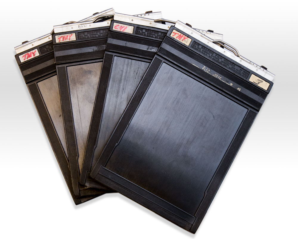
(5x4" film holders, 2 sheets each Jtknowles, wikimedia, public domain)


Uwe Aranas / CC-BY-SA-3.0

This film has to be developed manually. The developing process conceptually involves only a few simple steps: go somewhere absolutely dark, remove the film from the holder, submerge it in developing chemicals for the right amount of time, rinse with mild acid to stop the developing, then submerge in a fixer chemical, which stabilizes the image and makes it light-insensitive. Rinse again, and dry, and you have a negative.

There are many interesting details to all this that I will explore in other blog posts: the science and process of how to determine your developing times and chemicals, how to test and calibrate this for a given film, where I got giant sheets of film to begin with, what the tilting and pivoting parts of the camera (80%-90% of its hardware) is for, how to digitize large negatives, etc. etc. For now I'm just going to finish up with a description of my darkroom setup, though.

I have nothing remotely approaching the space for a dedicated darkroom. I live in a small one bedroom apartment. But you don't really need a dedicated darkroom unless this is your full time job. All you need is a place you can make very dark with chemical resistant surfaces in it. For me, this was my interior bathroom, which has no windows and opens into a hallway:


Not shown is the doorway, which I sealed with double flaps of painter's tape in opposite directions--one on the frame, one on the door--to force any light to pass through an "S" curve of tape, which stops nearly all of it. I also threw a towel on the bottom of the door for good measure. It is PITCH black in there with the lights off just from that, even after 20-30 minutes of letting your eyes attempt to adjust. Darkness is actually not difficult to achieve.

Other parts of my setup:

A) You can see some film holders with film inside ready to develop on the side of the tub. It looks like I only had 4 sheets of film (two cartridges) this session.
B) Containers of concentrated developer chemical and a jug of DISTILLED water to the left. (I was not using that blender pitcher for anything other than clean water...)
C) A graduated cylinder for measuring out precise dilutions, and rubber gloves -- developer isn't incredibly dangerous, but safety never hurts. I also wear goggles, and have a fairly strong bathroom vent fan on at all times.
D) I bought a number of these convenient half liter or so plastic containers. Before turning the lights off, I pre-fill them in order with everything I need. Developer, mild acid wash (just dilute vinegar), fixer, and water, and arrange them on my tray in memorized locations. I also cut small scores into the bottles with a knife that I can feel in the dark with my thumb to identify which chemical was inside.
E) The actual film I developed in PVC tubing. The inner circumference of this tube size is perfect to hold a curled 5x4" film sheet without overlapping itself. The developed side faces inward. You can see the tube is coated in black duct tape, because even light that gets through solid PVC can be enough to mess with the film if the lights go on or the door opens (like if I need to step out to answer the phone, etc.). The pipe is capped on both ends, caps shown next to it. This long pipe holds two pieces of film in a row.
F) I have a red lightbulb on the shelf here. It turned out not to be safe for the film to have on constantly, but for parts requiring fine accuracy of pouring, I sometimes flip it on briefly. The book shields the film area from any direct light, so it's only light that bounces that arrives there. Mostly, though, I work in complete darkness with just practiced movements.
G) A simple piece of twine and some binder clips works great for drying  developed film. This is where the DISTILLED water becomes important: tap water won't screw up the chemistry, but it will leave spots of minerals on your film when it's dry, which will show up in the final image. Distilled water leaves nothing behind. The binder clip doesn't mar the image, because the very outside of the film isn't exposed--it's where the holder holds it. You can see this outline edge portion in the example photos further below.


Darkroom with low intensity red light on

Again, I'll be putting up several more posts including discussion of how to actually calculate and test developing times and chemicals and all sorts of processing steps, with many examples of the kind of results that come out, but for now, here's one example of a 5x4 developed film photo of a local hydro/gas power plant (inverted in photoshop to a positive image):

Notice I added a box in photoshop in the middle. See the top bit of that brick building in the box, with the three prongs sticking out of it with shadows cast from them? You can barely even tell it IS a brick building in the image above. But here's a higher resolution (still not full res! But you can start to see the fuzziness now) detail of a tiny bit of that brick building and one of those prongs:


Now suddenly you can review the consistency of the masons' mortaring job on individual bricks... Yeah, large format film is amazing. And this is with a bargain basement $50 or something throwaway lens, too, and film designed to be used in x ray machines, not for fine photography. It could get crisper still with professional materials and equipment. This is also a detail in the center of the image, where most lenses are good. My terrible one I used here gets very soft at the edges, while a high end lens would not.

One more example photo:


Tuesday, December 8, 2015

Backstrap Loom Weaving

Hello again everyone! I am recently finished with my doctoral training and in a new job and back to crafting again. Well... technically, this post's topic of weaving I originally started as a stress-relieving activity during the height of my studies. Weaving is meditative and creates satisfying, well-ordered structure in front of you with minimal mental gymnastics. At least if you're not making any complex fabric.

"Weaving" probably initially brings to mind images of gigantic, unwieldy, wooden looms taking up half of one's living room. And indeed, if you want the height of industrial efficiency, stylistic freedom, and ease of creating different finishes and textures, that's the way to go. But I was A) poor, B) didn't have 100 square feet to spare, and C) just wanted a relaxing craft activity. So I chose to use backstrap weaving techniques:

Backstrap weaving (image by Infrogmation, GNFL license)

Backstrap looms, like the one shown above, are cheap to make, requiring only cords, straps, a series of wooden dowels and slats, and some spare lengths of the same kind of yarn used to weave. The fabric you are making itself holds the loom together otherwise. When not in use, the whole project can be rolled up and stored. While in use, the loom is held together by placing tension on the warp yarns (vertical to the weaver) with your body, leaning back and stretching them between yourself and an anchor point in front of you. Dowels then keep the yarns separated while you weave the weft yarns (horizontal to the weaver) back and forth between. As you finish sections, you partially roll them up on the bar nearest you so that the next section is in reach, and so on until finished.

I didn't start with anything as ambitious as the woman above's yard-width cloth. I started by making a simple, thin, acrylic yarn strap. Below is a third party technical diagram of a backstrap loom, followed by a photo of my actual homemade one:


The warp threads are actually one continuous loop back and forth between the two anchor points of the loom, at the body and the far end. The warp threads can be seen splayed out at (A, furthest from the weaver) in the image. These tend to get tangled on their own, though, so to help prevent this, I made a "cross" (B) in the yarns by weaving a simple stick between every other thread, then weaving another one between the opposite threads (actual cross is between the sticks at B). This forces any tangles to resolve themselves and leave the yarns in order and well-spaced going toward the working section of the loom. To help keep the yarns spread out and untangled, tension is applied by the bar near the body (C), which is attached to a strap around the weaver's back (not shown, though notches are visible for the strap to attach). Two sticks are used here to allow the finished work to be rolled up as progress is made, without unrolling from the tension.

Then the actual process of weaving involves taking another length of yarn, the weft, and passing it through all the odd numbered yarns, then all the evens going the other way, back and forth. The weft thread is all rolled onto a bobbin (D, I used a knitting needle) so that passing all of it through the warps doesn't take an hour each time. The working edge of this piece of cloth is at (E); you can see where the weft has made it to so far. The stick right at the working edge is used to "beat down" the weft toward the finished cloth after each pass to make it nice and tightly woven.

How does the weft get between opposite yarns each pass? Well, you could thread it through each time manually, but that would be horrible. Instead, there's a system to quickly shift all the even numbered yarns up and then all the odd ones, quickly and efficiently. The odd numbered yarns are held apart by a nice thick bar (F) at the back of the loom. The even numbered yarns are then each individually tied to little strings ("heddles") that reaches down through the odd yarns, and then attaches above to a stick (G). To raise the odd yarns, the thick bar (F) is moved back and forth and up and down to well separate those yarns, while the heddle strings allow the even yarns to pass below without getting in the way. This creates a triangular space between (the "tent"). The beater stick (E) is placed inside (it is removed and replaced each pass), and flipped on its side to make the tent even bigger. Then the weft bobbin (D) is passed through. The weft is beaten down, and the beater stick removed again. Next, the thick bar (F) is pushed back out of the way, and the stick with all the heddle strings on it (G) is lifted, PULLING all the even-numbered strings through the odd ones so that they are now on top. The beater stick is put in again, the weft bobbin passed the other way. These two phases are repeated over and over again until a cloth is formed.


Above is the finished result of my first strap. If you look very closely, you can see several characteristic errors made by people who don't know what they're doing. For one thing, one end is about half as wide as the other. This is called "pulling in" and it results from not leaving enough slack in the weft thread as it is woven through the warp. When it gets beaten tight, the weft is crimped, and thus shortens. If there's no slack, this pulls in the sides of the whole cloth, making it progressively narrower. The way to fix this is to leave the weft at a slight angle before beating it tight, so that it is a bit longer than the width of the cloth, leaving room for crimping.

You can also see that at the edges, the texture changes in places. It becomes more square looking, while the middle of the strap looks hexagonal. This is because the warp yarns at the edges were looser than the ones in the middle. I didn't have even tension across my whole width. Thus, the warp and weft at the edges are about equally tight and pass over one another equally, while the warps in the middle are much tighter than the wefts, so one of them crimps and the other doesn't, leaving the hexagonal look as you can only see one of them. On the sides you see both warp and weft.  My next attempt was a lot better:


Here I was making a small patch of a twill fabric (specifically a gabardine). The first strap I made was a "plain weave", over under over under. In a basic twill, instead of having all the odd yarns alternate with the evens, what you do is pass over TWO warp yarns, then under two, then over two... Which two you pass also shifts over every time you send the weft through, like this:

Twill Weave (by Jauncourt, CC Attribution Share-Alike)

If you imagine counting off every warp thread as 1,2,3,4,1,2,3,4... this means that depending on the pass of the weft, you need to variably lift all the 1's and 2's, then next all the 2's and 3's, then 3's and 4's, and finally the 1's and 4's. Four different sets of yarns need to be controlled instead of the two sets for the simple strap I made. This means that I need not just one thick bar and one set of heddle strings, but instead one thick bar and THREE sets of strings. This way, I can achieve all four types of lifted sets of strings. You can see the three different tied sticks in the photo above. This is trickier to set up, but not much trickier to weave. I'm using orange yarn for the warp this time, and red for the weft, so that you can tell them apart later.


Here's one side of the finished product (above). Notice that you can ONLY see orange. This is a "warp-faced" fabric since on the intended display side (above), you can only see the orange warp yarns. The red wefts are hidden underneath. Notice also that the cloth looks much denser and tighter than the strap earlier. Since the yarns aren't crimping as much as in a plain weave (only every two yarns not every one), more yarns are packed into a square inch than in a plain weave. This makes twills harder-wearing and popular for work clothes and jeans. The tight weave also makes twills more insulating (jeans are generally warmer than linen pants, which use plain weave), and easier to waterproof. Gabardine, the weave I made, is popular as an outer weave for raincoats, for instance.

Here's the back side of the same cloth. On the back, you can see the warp and weft about equally well. This is not the "face" of the cloth, though, so it's still called "warp-faced." Notice that the width doesn't change quite as dramatically as last time, but I still pulled in a bit from start (left) to finish (right). The tension is more even this time. The edges are also more consistent, from repetitive practice.

Next, I used a mixture of stiff hemp warp strings and soft acrylic weft yarns, and chose a new pattern: a diamond twill. This is a normal twill, but with the pattern simply changing direction in blocks. When tying the warp strings, I changed the pattern partway, and I also changed the direction of which heddles I lifted occasionally while weaving to make the pattern change the other way as well. Here's the loom set up first, followed by a diagram of a diamond twill.


If you look closely, this looks just like a normal twill but in smaller "blocks" that flip occasionally.

Again, this pattern required 4 types of yarn lifts, so a bar + 3 heddles, varying which sets of warp yarns were lifted as I went. The finished product is below, with a bit fancier finishing of the ends. You can see the diamond pattern, though it's not a consistent looking as I'd like. You can see both hemp and red yarn here, because even though it's warp-faced, the yarn is so much bulkier that this balances out the tension visually and keeps them both more equally visible at once. Notice that when I cut the bottom, it by no means immediately unravels. These cloths could definitely be cut to patterns and used in sewing if large enough.


It takes me about 20 minutes to wind the warp yarns around two pipes in a wooden board and transfer them onto the loom, then anywhere from 30 minutes to hours to tie the heddles depending on complexity and width of the cloth, and about 5 minutes per inch of cloth to weave the weft along. Next up is going to be attempting a much larger piece of fabric, like a dish towel, perhaps. I also want to try out changing the warp and weft colors across the fabric, such as when making a plaid fabric.

Much fancier and irregular patterns can also be woven into a cloth, like the shapes of animals, but this requires manually "dropping" or "picking up" yarns in violation of the background pattern as you go, and it is very painstaking by comparison to plain fabrics like these.

Tuesday, December 2, 2014

Making Potash


"Potash" is a vague term referring to any of a variety of soluble compounds of alkali metals, mostly potassium carbonate, potassium chloride, sodium carbonate, or sodium chloride. All of these compounds can be found in burned plant ashes as a portion of the leftover non-flammable, non-volatile material left after burning.

I desire potash for one reason: it acts as a flux for silica compounds. I will use this in two different other projects. First, as a glaze for pottery that can melt and seal ceramic items without the underlying item melting, thus allowing me to waterproof earthenware mugs and pots. Second, to lower the melting point of quartz for making glass at reasonable temperatures.

When you burn things to create ashes, though, a lot of other substances also end up in ashes:
Iron oxides
silicon oxides
aluminum oxide
calcium oxide
magnesium oxide
manganese oxide
phosphorus oxides
unburned charcoal

The ratios of these and potash depend on the species burned. Willow wood yields a whopping 50% potash, and very little silicon or aluminum. English oak yields 23% sodium and potassium compounds. Rice husks only provide 1.3% potash, etc. I am using leftover ashes left over after other clay project firings, and I don't know the species. This is bad for achieving a consistent pottery glaze. Later, I will want to source a consistent supply of ash, but right now I'm happy with ANY result.

The best way to separate our desired potash from the other substances in raw ashes is to exploit potash's solubility. So first, we shovel some ash into a container, (I strained through a cheap spaghetti colander first to get rid of large chunks), flood it with water, and let it sit for a couple of days. It will look like this:


In the photo, the liquid on top is full of potassium, sodium, hydroxide, and carbonate ions, which we can now pour off into another container for further processing. The solids at the bottom are the non-soluble oxides that would ruin the melting point-lowering properties of the potash.

Don't get greedy. Don't pour off the liquid before the solids have settled, and stop pouring when you start getting any ashes pouring out. The non-soluble ashes will be counter-productive, because they are highly refractory and will raise the melting temperature of whatever you're making.

Careful, the poured liquid is highly caustic. It is not a cellular poison in the sense that something like cyanide is, but it will chemically "burn" you (turn your skin into soap) if you get it on you and don't wash it off quickly. Wear eye protection and gloves when pouring, and flush any splashed skin with large amounts of water. Treat this liquid as essentially Drano.

By the way, save the byproduct solid ashes. For two reasons: One, you can refill with water and repeat the process again for more liquid from these several times. Two, once you're all done, the remaining washed ashes are wonderful for making fire bricks for furnace linings, because all the remaining materials are very resistant to heat and have very high melting temperatures.

Anyway, back to the liquid: letting this air dry is ineffective, because crystals will start covering the water surface and prevent evaporation. Boiling the water off works better. The amount of water you see at the top of the jar poured into a pan and boiled dry yielded this:


Again, these crystals are caustic. They will re-dissolve and saponify your skin if you get them on you with any moisture (like sweat). Be careful. That said, I unceremoniously scraped mine off with a spatula. The potash won't ruin your utensils or pot, and you can use them for food later, as long as you VERY thoroughly rinse and wash the potash off first. Tiny trace remnants that remain after going through a dishwasher or a good scrubbing will not hurt you, they are not toxic beyond being strong bases. Think of it like having Drano or bleach in a pot temporarily -- you wouldn't throw out the pot, but you would wash it well before cooking with it.

At the end of the day I disappointingly ended up with this much potash from one pouring of the container liquid:


These aren't exactly fluffy white crystals, but that's okay. It might be just that there are several compounds mixed here, so they inhibit one another's crystal formation. Since all of the hydroxides and carbonates are useful, though, this is not a problem. We don't need to separate or purify them individually (also, the crystals are still damp in this photo).

Don't put the potash on aluminum foil. It will react.

This is only one pour off the jar of ashes. You should be able to continue getting potash for many pours in a row, leave a day or two between each one, until you stop getting justifiable returns. My second pour-off a couple of days later yielded about 75% as much as the first, for example.

The potash will lower the melting point of clay it is mixed with. So when mixed with crumbled dry clay, ground up, mixed with water, painted onto a piece of ceramic, and left to dry, the surface mixture will melt sooner than the underlying clay piece, creating a glaze. I will cover this topic in more detail in a future blog post, but I have already achieved early success in using my potash to make glaze. The black corner of the right side piece in this photo is vitreous glaze made with the above crystals and clay powder. If/when I can cover a whole piece with successful glazing like this, I will be able to make waterproof items:


Sunday, November 9, 2014

Homebrew Pottery - Firing local clay


SO! I have now found some local clay and I have figured out the best amount of tempering to use. I also mixed up my pure clay with some different additives for the purposes that I wanted.

Now it's time to fire the clay into true ceramic! Several processes are involved, but mainly, the firing process mainly drives out water (only some water evaporates, and the rest is physically trapped or chemically bound), burns off organic material, changes the crystal structure of quartz components ("quartz inversion"), and sinters particles together.

My "kiln" at the moment is nothing but a Weber grill. The temperatures on the rack where you would normally put food only get up to maybe 600-800 degrees, but by completely burying clay wares in charcoal, the temperatures can get up to the roughly 1800+ degrees needed to begin to make true, low-fire earthenware ceramics (bisque temperature). The whole heating process needs to proceed SLOWLY. For more information, google "firing schedules." Details are beyond the scope of this blog, unless people are interested.

I'm firing simple bricks for now, to be used later as kiln components for a proper homemade ceramic kiln. The orange bricks in the photos are ones I fired earlier, and have painted with a homemade ash glaze as test pieces for glazing. This is simply part potash and part local clay, mixed with water and painted onto the pieces then left to dry in place. You can see the grayish ash on top of them (see future blog posts for more details).

First, I heat up the bricks around the outside of the grill, as the coals are lighting. This very gently brings them up to ~150 degrees over the course of half an hour to an hour, driving out as much water as possible without creating expanding steam that might crack the pieces:


Next, I move the bricks into hotter and hotter zones, eventually leading to a pile in the middle. This brings them closer to maybe 400 degrees, driving out the last bits of chemically bound water.


I remove the grill and very quickly (lest the pieces start cooling off) add more fresh charcoal to the fire to make a nice bed. I pile the pieces back on top of the new charcoal bed and leave them there for maybe another half an hour or so. You can see in one of the photos below that open flames are visible from organics burning off, and the bits of grass are charring away. this is somewhere between probably 600-1000 degrees. 

I did this part too quickly still and caused some black charred-looking areas, which is a sign of too little oxygen and too quick of organic fuel consumption (it has to do with the iron in the clay body reducing), but oh well, lesson learned for next time.


Once most of the organics looked burned off, I covered the pieces entirely with a layer of lump charcoal. This decreases oxygen access, so AS SOON AS POSSIBLE they need to have a forced airflow added to them at this point, or further "black coring" will occur, which is bad for your clay. I had a box fan pointed at the fire when I did it at this point, but this was probably not enough.


The upper charcoal is lighting, and you can see the red-hot core of the inside part of the grill where the pieces are. Open flames are still visible, but at this point I wouldn't be too concerned about it being organic material, it's probably just the charcoal itself. This is dull to cherry red glow around 1500 degrees maybe at this point:


The firing continued into the evening hours. The internal temperature is now sufficient to create bright red to orange hot ceramic pieces inside, as you can see in the photo where I briefly lifted the lid off to show a brick inside. This bright orange to almost yellow glow is probably somewhere around 1800 (+?) degrees. During this time, I was blowing air into the fire from a squirrel cage electric powered fan, positioned underneath through the ash collection hole, firing oxygen up through the fire. I got lazy and was inconsistent with this, but it really should have been going continuously, all the way until the fire burned down, if I wanted the strongest pieces. Since I let it go without forced air for awhile, it further reduced more of my clay's iron and made the pieces more brittle than they should have been.


This temperature was held for maybe another hour or so, adding charcoal as necessary. After that, I let it die down on its own all the way until cool (several hours). Then I removed the bricks and took the photo you see below. The bricks have been successfully made into true ceramic, with their oxidized iron components giving them a familiar brick hue. The especially light color is no doubt due to the sand mixture I added.

The gray/black spots you see are reduced iron from me being impatient with my firing schedule and not using enough forced oxygen. These reduce the strength and effectiveness of the bricks and are to be avoided.

Generally, the bricks were very brittle, probably too brittle to use. Not just from black coring, but from probably using too much sand and grass clippings in the mixture. Just from touching them, it is OBVIOUS though that they have huge insulation value. The bricks are very lightweight and very porous from the burned away grass, almost like pumice. All those tiny air pockets make them more effective at insulation, at the expense of fragility. These need a higher percentage of clay overall, because the balance is too far toward fragility, but it's a minor recipe tweak.


The other three pieces were ones that were fired earlier, and simply had glaze applied to them. You can see how they hold specific shapes much better and have little or no porosity, because these pieces were 100% clay in composition (on the inside/main body). You can also see how they are redder in color due to higher iron content when sand and grass are not mixed in.

The glazing experiment was a partial success. From left to right in the image below, glaze mixtures with a lower ratio of clay slip to potash are shown. The highest clay content on the left strangely seemed to have burned away completely, or perhaps got scraped off by accident, this one is confusing. The other two are as expected: the medium mixture in the middle looks like I just painted more earthenware right onto the block. This is no true glaze, and won't help to keep water out, etc.  But the high-potash content piece on the right shows signs of JUUUUUST beginning to form an actual glaze in the upper left, and a near-glaze (white) elsewhere. The black corner is actual glass, and is proper, waterproof glazing!

Getting the whole piece to be consistently covered will require a combination of just a slightly thicker coat of glaze painted on, a couple hundred more degrees of temperature, and probably more potash in the recipe. The more potash you add, the lower the glassifying temperature, but the more fragile and likely to crack (and harbor bacteria) the glaze is, so this is a careful balancing act, but I feel confident now that an actual waterproof glazed mug is within my abilities!


Next steps include making a more proper kiln with insulative lining to get hotter temperatures, adding better airflow and oxygen control throughout the process, and fixing the glaze and brick recipes.


Saturday, October 11, 2014

Let's Build an Organ Pipe!

Part one here!

In this post, I'll go step by step through my process for creating an (unpainted) PVC organ pipe! An organ pipe has two parts: the resonator, which is most of the length of the pipe as a simple empty tube, and the fipple, which creates oscillations.

THE RESONATOR 

The resonator takes vibrations (or perhaps more accurately, oscillating air vortices that I don't entirely understand) from the fipple and resonates at a fixed, controllable wavelength, allowing specific tones for music. Each pipe is going to produce one fundamental tone, just like individual strings in a piano. A single pipe will create several other tones at once when sounded, equaling integer multiples of the fundamental frequency (harmonics). The smaller the pipe, the more prominent the harmonics, but the fundamental is always the strongest.

Here are some different harmonics fitting into a single pipe (top three waves) and a fundamental of a longer pipe (bottom), with distance from midline being relative min and max pressure for each one:


However, less so than composers, we don't need to concern ourselves much with harmonics for building the organ. The pipe will sound like the fundamental frequency when you play it. So what matters more for us is the bottom of the image above: When you make a longer pipe, it will naturally resonate at a longer fundamental frequency. Longer waves are heard as lower tones. So by making different length pipes, we make different notes.  One half the length of pipe = one octave lower, and other notes vary by even logarithmic steps in between. In other words, human perception varies logarithmically with frequency.

So the resonator, at the end  of the day, is just an empty tube of the correctly calculated length. I'm making mine out of PVC pipe. For tuning purposes, I also have slightly larger pieces of pipe on top that can slide up or down to make fine adjustments to the lengths for tuning.

Middle C is an open pipe of about 2 feet in length, as a point of reference. A concert tuner of the A above middle C at 440Hz is about 1.28 feet long. 

Closed pipes (with a stopper at the end) have twice as long of waves, roughly, because the wave has to "reflect" the length of the tube then back again from the fipple. A closed pipe sounds one octave lower than it normally would, so middle C would be about a 1 foot long closed pipe. This is useful if you want to fit big pipes in an apartment building.

THE FIPPLE

The fipple is the vibration producing part of the pipe. I'm going to be routing air to my pipes by plastic tubing, so it needs to convert a stream of pressurized air from a circular tube into a consistent vibration. The fipple is much harder to make than the resonator.

Briefly, the concept of a basic flue pipe fipple (meant to sound something like a flute) is:
  1. You somehow shape incoming air into a laminar air flow (a flat, non turbulent sheet of air).
  2. You get that flow to pass right into a thin knife of rigid material, which will then vibrate.
  3. The vibration resonates in the resonating chamber.
The way we make those things happen is by building something like this:


The pipe (red) has a cap on the end (black) with a hole for the air hose (green). There's also a plug in the pipe (orange). Air comes into the cavity in the back and has nowhere to go, except for a narrow section of pipe cut away at the top. This forces the air into a sheet, which passes over and under a knife shape cut in the pipe (red also). This vibrates, which then causes resonation in the pipe (left off the edge of this image). Again, I think it is more like oscillations of swirling air systems in a much more complicated way than just vibrating, but that's close enough for me to build it.

So without further ado, let's build it! We begin with a PVC plumbing pipe:


First, we need to cut a notch out of the end. The width of the notch is related to the diameter of the pipe, something around 2/5 the diameter. The depth of the notch depends on the system you're using for a cap. I used this tool here, a dremel with a grinding fiber/ceramic/something wheel:


Here's the notch cut out:


Then I used a much wider grinding stone (seen below), 100 grit sanding drum (not shown) and finally manual 220 grit sandpaper (not shown) to grind a sharp, gradual "knife edge" on the inside of the notch. Grinding stone:


Knife edge after all the dremeling work:


Knife edge after hand sanding:


We need a laminar sheet of air now. I achieved this by using the thickness of the PVC pipe wall itself as a guide for a sheet of air. So I need to block off the inside diameter, AND the outside diameter. The inner diameter is blocked using this section of a solid plastic dowel rod:


The corner is sanded down to aid aerodynamics (the air needs to be smoothly guided toward the knife). The plug fits into the pipe snugly. Notice how the pipe walls stick above the plug, so that when the cap goes on later, there will be a thin slice of opening:


A hole is drilled in the middle of the pipe cap. This is where plastic tubing will go to deliver the air supply:


And finally, the cap is attached. If you look closely, you will be able to see the thin slice of empty black space in between the plug and the cap nearest the camera. This is the guide for the airflow to make it into a sheet of air. It will then pass right into the knife edge, creating the musical vibrations, which resonate in the remainder of the organ pipe:


Again, here's the schematic now that you've seen the real thing:


NEXT TIME

In the next installment of this series, I will explain how the air system works, and I think I'm going to actually try out a new idea, different than my original plan, for how to activate air flow to individual pipes. I will try experimenting with homemade electric solenoids, versus the alternative of manual springs and levers and things.  If the electric version works, then the whole organ could be played either manually OR by computer program, potentially!